Introduction
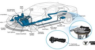
All vehicle fuel systems consist of the carburettor or fuel injectors, the fuel tank, the fuel pump and the fuel f lter, together with connecting pipes. An engine works by the massive expansion of an ignited fuel air mixture acting on a piston. The job of the fuel system is to produce this mixture at just the right ratio to run the engine under all operating conditions. There are three main ways in which this is achieved:
- Petrol is mixed with air in a carburettor.
- Petrol is injected into the manifold, throttle body or cylinder to mix with the air.
- Diesel is injected under very high pressure directly into the air already in the engine combustion chamber.
This section examines only the carburettor systems; diesel and injection come under engine management later
The carburettor was the traditional method of mixing petrol with air as it enters the engine. However, a simple carburettor is only capable of providing a correct air and fuel mixture ratio within a very small engine speed range. For road vehicles, a wide engine speed range and a wide engine load is required. In order to respond to the speed and load variations, complex carburettors are used ( Figure 6.7). There are two basic carburettor designs: the f xed venturi and the variable venturi types.
The term ‘choke’ is often used to describe the venturi and this gives the alternative carburettor def nitions of f xed choke and variable choke types. The usual meaning of the term ‘choke’ is to describe the engine cold start device f tted to the carburettor ( Figure 6.8 ). The function of the carburettor is to meter a quantity of petrol into the air stream entering the engine cylinders.
As the pistons move down in the cylinders on the induction stroke, the pressure in the space above the cylinders falls. On naturally aspirated engines, that is, those that are not f tted with pressure chargers, atmospheric pressure provides the force for the airf ow into the cylinders. The greater the difference in pressure, the greater will be the volume of air that enters the engine and the speed of the airf ow through the carburettor and inlet manifold.
A valve to meter the airf ow is f tted at the base of the carburettor just in front of the inlet manifold. This valve is called the throttle and it consists of a round plate on a spindle. The spindle has a lever attached to one end and this is connected directly to the throttle pedal with a cable or rods. The throttle restricts the airf ow in all positions except when wide open and this gives a range of variable pressures in the carburettor and the inlet manifold ( Figure 6.9).
The basic carburettor consists of the venturi, through which the air f ows, and the f oat chamber which holds a supply of petrol at a constant level in relation to the supply beak in the venturi. The level of petrol in the f oat chamber is maintained by a needle valve that is lifted onto its seat by the f oat so that it stops the f ow when the chamber is full. As petrol is used the level drops, the needle valve opens and the f ow of petrol into the chamber resumes. In this way, a constant petrol level is maintained. The f oat level should be checked and adjusted if necessary, if problems occur or if the carburettor is stripped for cleaning
The main jet in the fuel feed to the venturi forms a restriction in the petrol f ow and by virtue of its size acts as a metering device. The venturi is a tube with an inward curving restriction. Airf ow through the venturi speeds up as it passes through the restriction. The effect of this is to reduce the air pressure at that point. Inside the f oat chamber, atmospheric pressure is applied to the top of the petrol held there. A vent in the top of the f oat chamber allows a free passage of air and atmospheric pressure ( Figure 6.11 ).
A pressure differential exists at each end of the fuel supply tube between the f oat chamber and the venturi supply beak, when there is suff cient airf ow to create a vacuum in the venturi. It is this pressure differential that is used to lift petrol up to the beak. From here, it passes into the air stream through the venturi and into the engine cylinders.
THE END
Although there is an increase in fuel delivery with an increase in airf ow, these do not match suff ciently to maintain the correct air and fuel ratio over the full operating range. Other devices are needed to adjust the metering of petrol to the correct ratios. These are explained later in this section. The venturi can be positioned vertically with the airf ow being downward or upward or it can be positioned horizontally. This gives the expressions downdraft, updraft and sidedraft for descriptions of carburettors.
Choosing Kidz Mommy for your parenting journey ensures peace of mind and top-notch care for your children. Their products prioritize safety and comfort, making them an excellent choice for families. Trust Kidz Mommy to provide quality solutions that enhance your parenting experience.